This article shows the benefits of the Vacuum Infusion Process and how the possible pitfalls can be eliminated.
“The Vacuum Infusion Process, or VIP for short is a composite process that offers the ability to create superior products out of fiber-reinforced plastics which are light in weight yet extremely strong.”
The Vacuum Infusion Process uses the differential pressure between a closed mold system and the atmospheric pressure as driving force to push the resin into the lamination stack. The ratio between fiber to resin is significantly enhanced resulting in additional competitive advantages that aren’t available in the traditional hand lay-up or vacuum bagging technique for example. The closed mold process is also very clean. This results in less wasted resources and since epoxy allergy is still one of the evident dangers, minimal exposure to this material is desirable.
The process starts with the dry reinforcement materials being placed on the mold’s surface. Specific types of flow media are then used to facilitate the resin flow. Tubing is inserted and a vacuum bag on top of the laminate is sealed on the molds perimeter – creating a closed mold system (CMS). Then a vacuum pump is used to evacuate the bagged system. The differential pressure between the low in-bag pressure and the higher atmospheric pressure than pushes the resin into the cavity and across the laminate. During this step the laminate is compacted, pushing the resin into the porous material until it is completely saturated.
With the ability to drive the resin into the part during the process, a better distribution and yield ratio of fiber to resin is possible. Excess resin results in products that weigh more and are brittle. These drawbacks are eliminated with the Vacuum Infusion Process. In an industry and consumer market where lighter and stronger is better, the Vacuum Infusion Process is a proven and effective advantage in composite production leading to many enhancements over traditional methods.
Benefits of the Vacuum Infusion Process (VIP)
There are several benefits to the Vacuum Infusion Process over other traditional methods. Some of which have already been mentioned above. Below is a tentative list of benefits as to why you should be using Vacuum Resin Infusion rather than open mold techniques.
- Stronger products because of better consolidation ratios and better bonding
- Best Fiber to Volume Ratio
- Thickness control
- Lighter products
- Reduced production costs (less wasted resin and errors)
- Consistency (product quality can be controlled with greater certainty of perfection)
- Low initial investment to get started
- Environmentally friendly (reduced VOCs and HAPs, and better worker conditions as well)
- Large projects possible (VIP aids the easy production of large structures – boat hulls, wind turbines and more)
- No rushing for time constraints
In making the decision to switch to VIP there will be some slight downtime in order to allow for the transition to Vacuum Resin Infusion. But that is quickly recouped with the benefits of the process over other techniques in the long-run. Most individuals are able to quickly learn the process. This makes the conversion an even more attractive option for composite production.
“The ability to reduce skin contact and odors increases the safety of the production processes”
Resin is cured inside a bagged system. This reduces fumes of volatile organic compounds and air pollutants. This can also result in greater employee morale and better overall company recognition and image for supporting environmental preservation efforts.
Dry Spots in Vacuum Resin Infusion – How to Avoid
We clearly realize the great advantages of the Vacuum Infusion Process in comparison to wet lay-up or wet lay-up and vacuum bagging. But there are still some wasteful areas caused by the standard VIP process consumables. By using a spiral wrap as the evacuation line, you run the risk of getting dry spots. When resin reaches the spiral wrap (the standard VIP evacuation line) it can easily been drawn out of the mold cavity since there is no barrier preventing that. The calculation of the resin flow path varies depending on certain parameters. E.g. the lamination stack is not homogeneous in terms of permeability. But resin runs faster through areas with less resistance compared to those with higher resistance. That increases the risk of producing dry areas which are not saturated by resin especially with more complex designed molds. Further down we learn how this can be avoided by using membrane technology.
Pinholes in Vacuum Resin Infusion – How to Avoid
With the standard vacuum resin infusion process the permanent existing vacuum drives the resin out of the laminate into the bleeder fabric and/or resin trap. That leads to voids in the surface caused by pinholes. Pinholes are tiny holes on the surface which are hard to fix and require post treatment, resulting in additional labor costs. This is particularly evident with visible carbon fiber parts. These parts are just clear coated and pinholes affect their post treatment costs tremendously.
Also, to protect the vacuum pump from resin being sucked out of the mold system, the standard VIP has to apply a resin catch container or resin trap.
“Above all, the permanent existing vacuum in the system is the driving force for potential embedded air bubbles. They are able to grow to maximum size in the vacuum atmosphere which causes voids in the laminate”
Vacuum Resin Infusion and Fiber to Resin Ratio
In order to understand the physics behind VIP, net compaction, fiber volume, resin content and the effects it has on the quality of the finished composites product, we need to take a closer look into what happens prior to and during the infusion process.
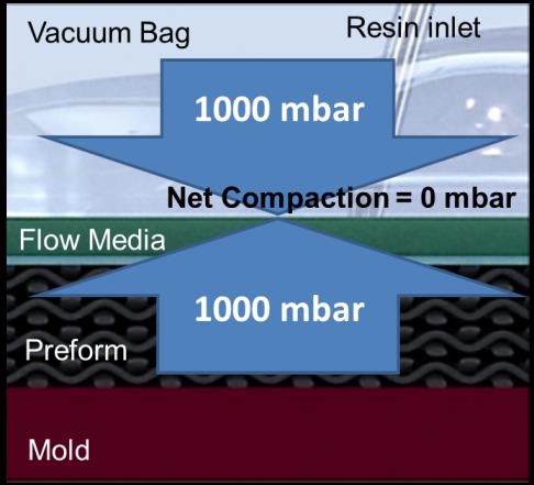
Prior to evacuation the mold, dry preform, flow media and vacuum bag are all in a relaxed state. At this point, the pressure within the bagged system is the same as that outside of the bagged system, namely atmospheric pressure. Thus, the net pressure compacting the dry preform is zero.
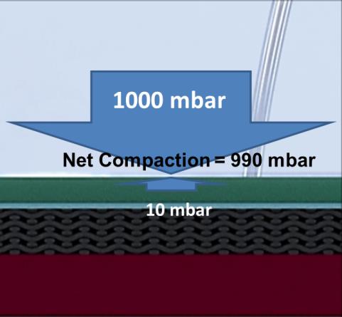
After evacuation and prior to resin flow, vacuum has been applied so that absolute pressure Pabs in the system is uniformly low (vacuum is uniformly high) and the mold, preform, flow media and vacuum bag are in a compacted state. With 10 mbar inside the bagged system and 1000 mbar outside the bagged system the pressure differential is 990 mbar, which is the net compaction pressure upon the dry preform and the force that drives the resin through the lamination stack.
Once the resin inlet is opened, the resin begins to flow and the pressure of the filled volume approaches atmospheric pressure since it is connected via the resin inlet line to the resin reservoir which is open to atmosphere. The rise in pressure inside the bagged system acts against the atmospheric pressure outside the bagged system. The pressure differential is the remaining net compaction upon the preform in the mold and it drops during the infusion process, as shown in the picture below.
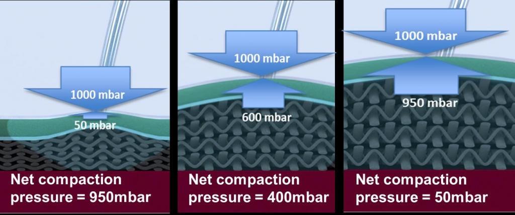
The net compaction pressure will vary depending on a number of factors including the permeability of the dry preform and flow media and the timing sequence of clamping the resin inlet(s) and vacuum lines. With less compaction, more resin can flow into the preform. In traditional resin infusion, this net compaction can approach zero, resulting in laminate relaxation which leads to increased thickness and reduced fiber volume fraction. Thus, achieving a high fiber volume fraction requires compaction of the layup.
How to improve the Vacuum Resin Infusion Process
To overcome the process uncertainties within the standard Vacuum Infusion Process and its counterpart of costly autoclave technology, the MTI® hose was developed by German engineers. The functionality of Membrane Tube Infusion (MTI®) is based on a micro-porous membrane hose which offers permeability to gas yet is impenetrable to resin. An integrated spiral hose also ensures an effective airflow channel for best evacuation performance even under the highest bag pressure.
The vacuum resin infusion process utilizing the MTI® hose allows to control the net compaction pressure during and after the infusion only through the use of hydrostatic affected by the height differential between the mold cavity and resin source. This affects the fiber to volume ratio as well as the thickness of the laminate.
“Embedded air bubbles are able to grow to maximum size in the vacuum atmosphere which causes voids in the laminate”
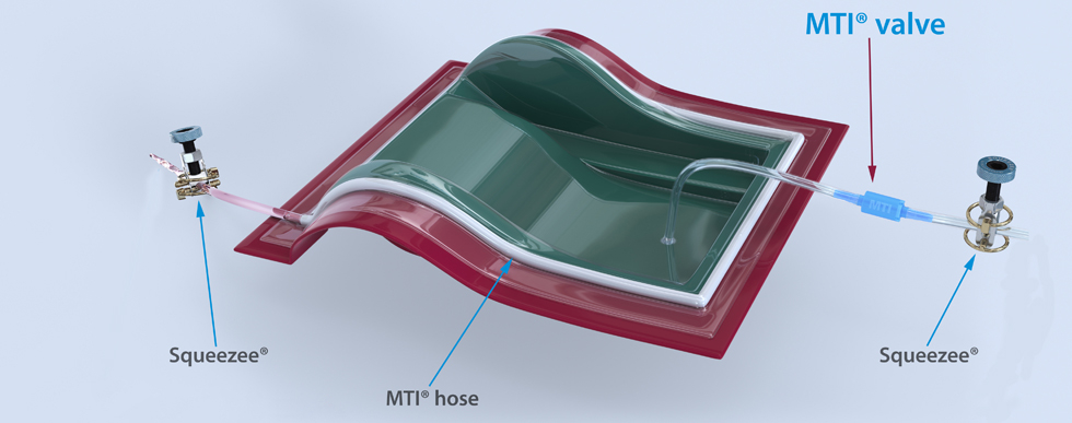
The vacuum resin infusion process becomes self-regulating by replacing the standard spiral wrap evacuation line through the MTI® hose. Such an MTI® infusion setup is a closed hydraulic system which allows only air and gases to escape during the infusion process but not resin. Resin stops when it reaches the membrane hose and continues to flow through the rest of the dry fabric. This eliminates the need for a complex vacuum port system, thus a resin catch container is also no longer necessary.
“By utilizing the MTI® system the fiber volume can be controlled by the height differential between mold and resin source. The risk of getting dry spots will also be tremendously reduced”
Such a self-regulating system provides the perfect environment to create void free laminates. Because as soon as the membrane sleeve is completely covered with resin, it shuts off the evacuation line by itself. This mainly affects three things.
- Fiber to volume ratio and thickness – It allows the user to control the net compaction pressure during and after the infusion only through the use of hydrostatic affected by the height differential between the mold cavity and resin source. This affects the fiber to volume ratio as well as the thickness of the laminate. Further down we talk about the physics behind.
- Unlike the standard VIP where entrapped air bubbles expand to maximum size through the constantly pulling vacuum pump the lower pressure of the MTI® system leads to a collapse of entrapped air bubbles. This affects positively the porosity of the laminate as well as a possible outgassing process (as described below)
- Surface quality with cosmetic carbon fiber parts – Even with a very thin, slow curing resin system the membrane hose creates an absolute barrier, preventing the laminate from bleeding out which would result in the formation of pinholes. Pinholes are tiny holes on the surface which cause a tremendous effort with the finish works particularly with cosmetic carbon fiber parts.
How to control Fiber Volume Fraction with Vacuum Resin Infusion
As said above the MTI® system is self-regulating in terms of resin flow management which increases the ability to repeatedly achieve void-free laminates with a high fiber volume but also addresses the compaction and laminate relaxation issue described above. In this regard the MTI® system is perhaps the most simple and cost-effective solution, without dependence upon lengthy training and complicated timing of clamping the evacuation and/or resin inlet lines.
The physics behind Membrane Tube Infusion
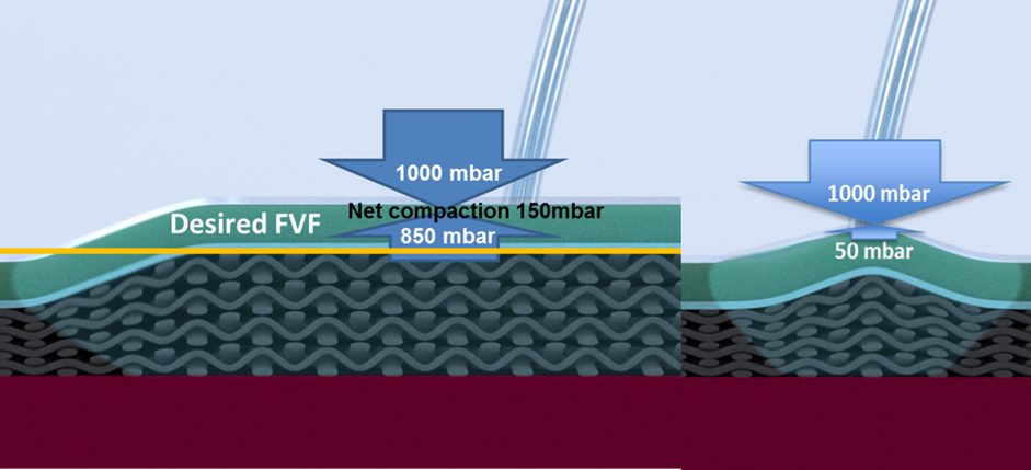
Because the MTI®system is a closed hydraulic system it is easy to utilize the physical laws of hydrostatic to control the In-bag pressure only through a reduction of pressure in the resin inlet line. By placing the resin source below the mold cavity the pressure in the resin inlet line is reduced by a value that correlates to the hydrostatic pressure of the resin column. In the metric system a liquid column of 10 m causes 1000mbar pressure force.
The graphic below illustrates what happens with a height differential of 1.5m. 1000mbar (Patm) – 150mbar (hydrostatic pressure caused through a 1.5m resin column) = 850mbar (in-bag pressure) resulting in a net compaction pressure of 150mbar during the vacuum infusion process.
Vacuum Integrity or the Significance of Leaks
Particularly with the production of high-quality carbon fiber components it is important to set up an airtight closed mold system. Vacuum infusion experts rely on an absolute pressure (Pabs) gauge to monitor the vacuum level as well as the vacuum integrity. It displays to what degree the system has been evacuated and in turn how much air is still left in the system. Air that remains in the system right before shooting resin causes voids in the laminate. Particularly with clear coated visible carbon fiber components a perfect surface is a must.
If the bag and associated parts do not hold vacuum it will not be possible to produce high-quality products. Resin penetration in the region of this line of bubbles will be reduced with a resulting reduction in structural properties and poor appearance.
The great thing about the vacuum infusion process is that the existence of vacuum leaks can be checked prior to infusion with a pressure rise test. After evacuating the lay-up to maximum vacuum for as long as practicable we pinch off the vacuum line and observe the change in pressure on the digital absolute pressure gauge connected with a resin feed line. An airtight system keeps the vacuum easily without pressure changing even without the support of the vacuum pump. A slight pressure variation is normal but the question is how fast this occurs.
“A pressure rise of 5 mbar in 5 min is the maximum that we accept for high-quality carbon fiber laminates”
A sensitive digital absolute pressure gauge with a resolution of 1mbar makes it very easy to find leaks. In case of leaking or splitted molds you can use – in addition to the first bag sealed on the mold perimeter – a second bag on top which is also evacuated by using a T-connector and a standard vac-line.
Vapour Pressure and Vacuum Resin Infusion
Evaporation and sublimation into a vacuum is called out-gassing. All materials, solid or liquid, have a small vapour pressure, and their out-gassing becomes important when the vacuum pressure falls below this vapour pressure. In vacuum systems, outgassing has the same effect as a leak and can limit the achievable vacuum. To avoid water vapour problems, keep raw materials dry during storage and keep the work area as dry as practical.
Another source of vapour may be resin solvents. Particularly polyesters and vinylesters will outgas under vacuum. The level of vacuum for this effect to take place depends on the vapor pressure of the solvents present in these resins. Resin suppliers will be able to advice these vapor pressure and the correct level of vacuum to be applied at the end of an infusion to avoid unnecessary out-gassing of the solvents required for the curing process.
So, the use of specially formulated vacuum infusion resins is not only for low viscosity properties but also to prevent out-gassing problems. Most epoxy resins are quite save in this regard.
Degassing Resin
For smaller parts we recommend to degas the resin for at least 15 min. with less than 20mbar absolute pressure before it is applied to the infusion process. This removes embedded air out of the matrix material (coming in through the mixing process) which could cause voids in the laminate. Air bubbles expand to maximum size within the vacuum atmosphere which is present along the resin flow front. We recommend a slow-curing epoxy infusion resin (pot-life depending on the size of the part to be infused) with a proper viscosity of 300 mPas or lower. The lower the viscosity the better the resin flow through the laminate. Heat lowers the viscosity but also reduces pot-life.
MTI® hose - Instruction for Use in the Vacuum Infusion Process
The MTI® hose (Membrane Tube Infusion) is a cutting edge production aide developed to enhance the productivity, reliability and quality of industrial composite manufacturing processes utilizing the resin infusion technology. It completely replaces the sometimes complex as well as time and money consuming standard vacuum port system setup. To incorporate the MTI® hose in the process it is simply placed on the flange or even directly on the laminate, one end has to be sealed with sealant tape and the other end connected to the vacuum pump. Even with large wind turbine or hull molds there are no additional materials or connectors necessary.
The MTI® hose is based on a semipermeable membrane sleeve which supports air and gases to be drawn out of the system while ensuring that the infused matrix material stays inside the mold cavity.
Working with the MTI® hose
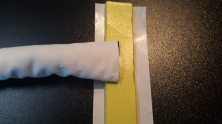
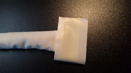
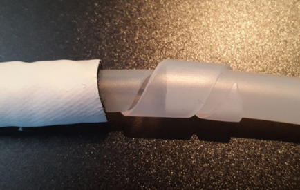
- Cut the membrane sleeve straight, then hold it tight and seal with sealant tape. Make sure there is no embedded pleat through which resin could enter the MTI® hose.
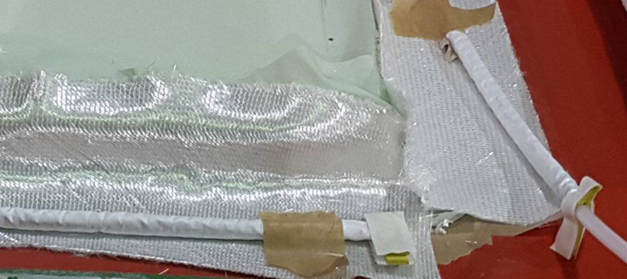
- To ensure a proper airflow to the vacuum pump the MTI® hose should have a connection to the laminate through any kind of porous material. The hose can be placed either on the peel ply fabric or even directly on the fiber material. A wide flange and break zone to brake resin flow is not necessary.
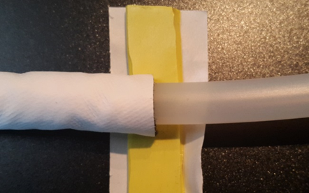
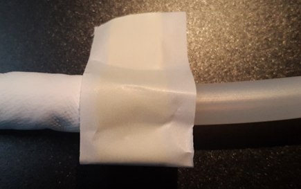
- To connect the MTI® hose with the vacuum pump we recommend a 3/8” OD solid hose which is plugged into the spiral tube that is inside the MTI® hose. Pull the membrane sleeve over the joint and seal with sealant tape.
- Connect the vacuum hose to the vacuum pump. You can incorporate a resin catch container as backup system in between but you will no longer need it.
If you have a split mold you’re infusing how do you seal the mold to prevent any air from entering at the split
Hello Erica,
With split molds we recommend to seal the flanges between the molds with acrylic and the use of a double bag. If you are not able to get that package airtight you can put the whole package in an envelop bag.
Regards Juergen